Hubert Jackson has created boxes for the University of Cambridge that enclose all the Amplicon hardware. They have the following connections:
| • | +28V DC in |
| • | 0V DC in |
| • | 78-way cable from Amplicon card in the computer |
| • | LED to indicate when power is being delivered to the front panel |
| • | 4mm connectors on the front panel. These are: |
| • | one black: ground (0 V) to devices |
| • | one red: switched power (+28 V) |
| • | white connectors: inputs (from devices to computer) - shorted to ground by the device to signal that it's on |
| • | blue connectors: outputs (from computer to device) - shorted to ground to switch on a device |
Lines 66 and 67 (or 138 and 139 if it's the second box attached to the computer) are failsafes. The server should be configured to turn 66 (or 138) on during operation and 67 (or 139) off.
Input (EX230) board wiring
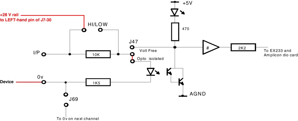
Hubert actually wired up the boards by removing the J31-54 jumpers and connecting a +28V rail to the left-hand pin of J31-54. See the circuit diagram. That effectively gives this:
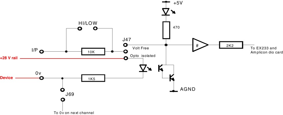
It certainly seems to work much of the time. Yet we do seem to have a high failure rate on the input boards. I'm a little concerned that this circuit bypasses the high-voltage protection resistor. I would have used a +28V rail to the left-hand side of J7-30, and had J31-54 connected left (as usual) and J55-75 open (as always), like this: