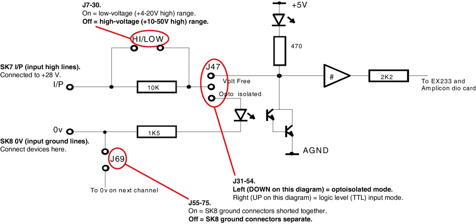
I will give examples for Med Associates inputs, which, when activated, short their control lines to ground (and share a common +28V line). Here's how we arrange things:
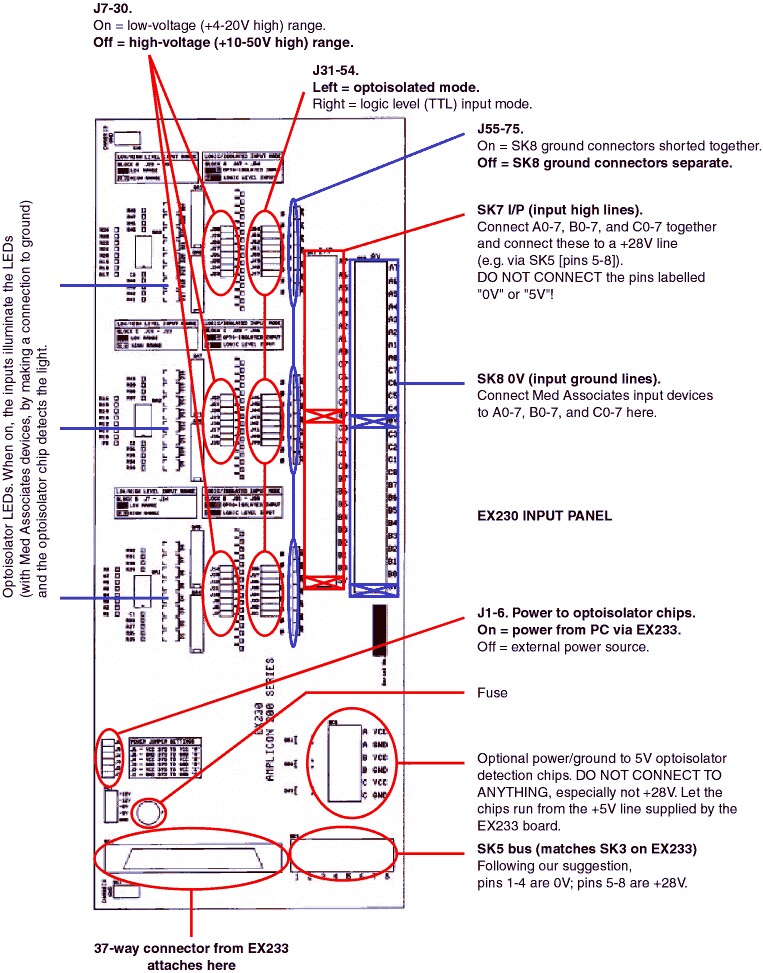
| • | So the board takes power from the computer, ensure jumpers J1-J6 are all CONNECTED. (See diagram below.) |
| • | To use 24V inputs, disconnect jumpers J7-J30. Don't lose the jumpers; attach them to one pin only. |
| • | To use optoisolated inputs, ensure jumpers J31-54 are all set LEFT. |
| • | So the ground connectors are all independent, disconnect jumpers J55-75. (Again, don't lose the jumpers!) |
| • | So the +28V lines are all shared, connect A0-7, B0-7 and C0-7 together on the "SK7 I/P" block. Pieces of paperclip are great for this, or you could use a single piece of wire. Then connect those lines to a +28V line. For example, pins 5-8 of SK5 should be attached to +28V if you have wired up the EX233 board as I suggested - but don't connect up the pins marked "0V" or "5V" in this block! You'd be shorting 0V or 5V to 28V, probably with some sparks. |
This is not as neat as we'd like - there's wire everywhere - but this is because the engineers at Amplicon expect people to share a ground wire and have separate +28V control lines, not the reverse. As optoisolators don't work if you plug them in backwards, we have to share the +28V lines by hand.
You will then be able to connect the data lines from the Med Associates devices to A0-7, B0-7 and C0-7 on the SK8 0V block (one line per device).
Ensure that the Med Associates devices use the same ground as the rest of the system.
Here's an annotated circuit diagram of a single input: