Med Associates devices are turned on by shorting their control lines to ground (0V).
| • | Ensure J1-J3 are connected, as per the diagram below. |
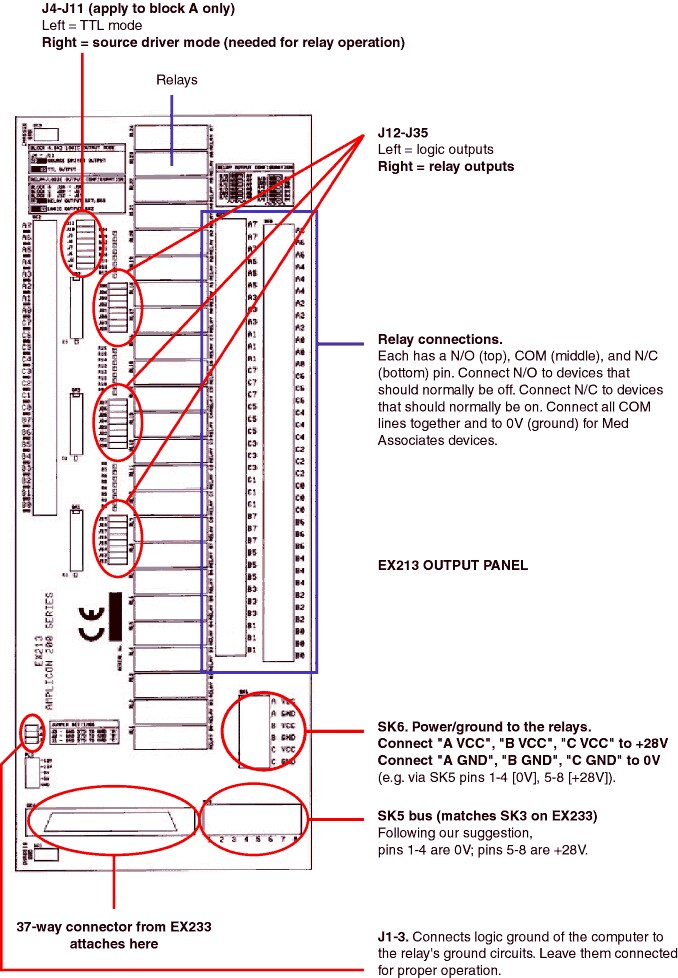
| • | Ensure J4-J11 are set to the RIGHT (source driver mode), as per the diagram below. |
| • | To use relay outputs, set J12-J35 to the RIGHT. |
| • | To supply ground to all the relay circuits, connect ground (e.g. SK5 pins 1-4) to "A GND", "B GND" and "C GND" on the block labelled SK6. |
| • | To provide power to operate the relays, connect +28V (e.g. SK5 pins 5-8) to "A VCC", "B VCC" and "C VCC" on SK6. |
Relays can be thought of as follows. They have a common (COM) pin. When there is no power applied to the relay, the COM pin is connected to the normally closed (N/C) pin, but not to the normally open (N/O) pin. When power is applied, this reverses (so N/O is connected to COM and N/C is disconnected). All the relays act independently and have separate COM lines, one per relay, but to simplify things for Med Associates devices, we want a shared ground:
| • | Connect all the COM pins together on the two long blocks (A0-7, B0-7 and C0-7). Then connect these lines to a ground line (e.g. pins 1-4 of SK5). |
Make sure that your boxes use the same ground, too (i.e. that they run off the same power supply). Then you can connect your device control wires to the N/O pins. This will keep your apparatus off by default. If you want it on instead - for example, if your supplier has wired a dipper so it's up by default and you want it down - you can wire it to the N/C pin instead.