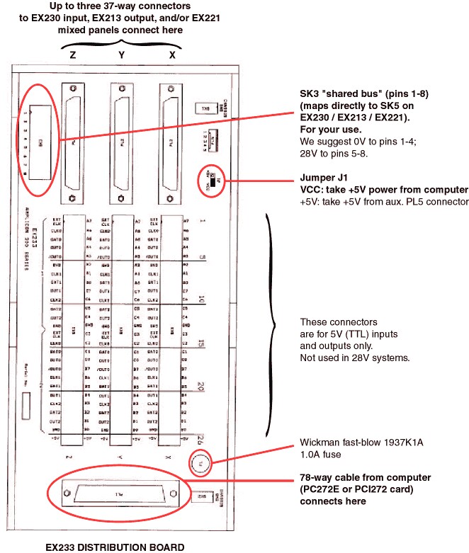
There's not a lot to configure on this board. See the diagram below.
| • | Ensure J1 is set to VCC. (This connects a 5V power signal from the computer down all of the 37-way cables. This will be used to power the optoisolator optical detection chips on input boards.) |
| • | To simplify wiring, use the "shared bus" facility of the distribution board. Eight connectors on the EX233 board, collectively labelled SK3, are provided for your own use. Whatever you connect to these is connected via the ribbon cables to an equivalent block of 8 connectors on any input/output panels that you connect to the distribution board (where they are labelled SK5 to confuse you). We need to share out +28V and 0V to all the panels. So wire 0V (GROUND) from the power supply to pins 1-4 of block SK3 on the EX233 board, and +28V from the power supply to pins 5-8. (This is an arbitrary choice, but I will assume you've done this from now on.) |