Configure hardware → National Instruments / Lafayette ABET hardware
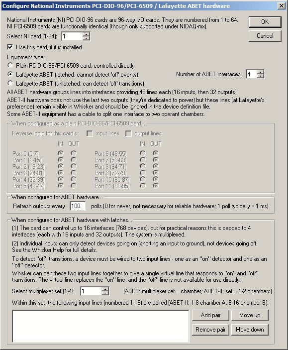
This configures ABET hardware from Lafayette (USA) or Campden Instruments (UK), based on the National Instruments (NI) PCI-DIO-96 card, itself based on the 82C55 chip.
| • | By default, the newer NI-DAQmx library is preferred to the older NI-DAQ Traditional library for communicating with NI cards. This option chooses the order in which the libraries are tried (tick for mx then Trad; untick for Trad then mx). |
| • | Select an NI card to configure. National Instruments devices are numbered from 1-64 by the driver software (e.g. National Instruments Measurement & Automation Explorer) supplied with the PCI-DIO-96 card. |
| • | Choose whether to use the selected device. It does no harm to attempt to use non-existent cards, so by default all cards are selected. |
| • | Choose whether the card is to be used on its own, as a plain 96-way digital I/O card, or whether it has Lafayette ABET hardware plugged into it, and of which sort. |
| • | If you have ABET equipment, specify the number of interfaces attached to it (from 1-4). Each interface communicates with 48 digital lines, of which 16 are inputs and 32 are outputs (though in some configurations only 30 outputs are actually used; see below). (The I/O card itself could deal with 16x48 lines using this multiplexing system, but there is a cap of 4x48 with the ABET multiplexer for practical and timing reasons.) |
PLEASE NOTE: The ABET hardware with latches cannot detect OFF transitions on inputs (input devices going off) using a single wire -- merely devices going on. To detect devices (e.g. levers) going off as well as on, you need to wire them to two inputs -- see below.
| • | If you are using the NI PCI-DIO-96 card as a plain 96-way digital I/O card, choose whether each of the twelve ports (numbered from 0 to 11) should be configured for input or output. Each port controls 8 digital lines. By default, the logic used by the card is the TTL system: +5 V DC means "on", and 0 V means "off". You can choose whether to reverse the logic for the input or output lines. |
| • | If you are using the ABET system from Lafayette, the configuration is very simple - all the details are handled for you. All you need to do, if you wish and if you have the ABET hardware with latches that cannot detect OFF transitions, is to configure pairs of input lines to be merged into a single virtual line that can detect devices going OFF as well as going ON. Full details are given below. You can add, remove, and re-order the pairs (re-ordering is merely cosmetic!). |
| • | Oh, one more thing (Oct 2009)... some ABET hardware is quite sensitive to static electricity (report from Lafayette, Oct 2009). To deal with this, Whisker can refresh the outputs (to make sure they're doing what they're meant to be doing). For ABET hardware, you can specify how often to do this ("Refresh outputs every X polls"). Typically, one poll is 1 millisecond (see Server > Set internal timer resolution). The default is every 100 polls (every 100 ms). Setting this to zero disables this additional hardware output refresh. |
PCI-DIO-96 card and cable connections to Lafayette ABET hardware
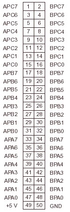
The NI PCI-DIO-96 card (provided by Lafayette as item 81404) is installed in the computer. It has a 100-way socket on the back. The card pinouts (for a NI 6508/6508/PCI-DIO-96) look like this (using the pin names as referred to by the NI-DAQmx software):
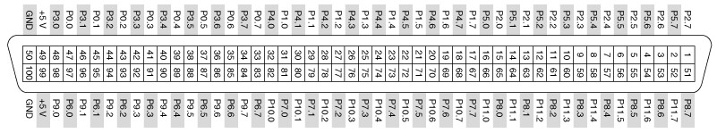
or, with different pin names (as referred to by the older "Traditional NI-DAQ" software):
Internally, the card has four 82C55 chips, each with 24 digital I/O lines. The card is addressed in terms of 12 ports, each with 8 digital I/O lines; each port is configured as a whole for input or output.
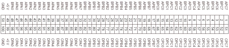
Each 82C55 chip can generate an interrupt upon a low-to-high transition of PC3 and PC0 (see the PCI-DIO-96 manual: Theory of Operation / Interrupt Control Circuitry). That means that wire APC0, APC3, BPC0, BPC3, CPC0, CPC3, DPC0, DPC3 can generate interrupts.
If you are using the ABET hardware, then into the 100-way socket is plugged a cable (an R1005050 cable) that ends in two 50-way plugs. Their pinouts are as follows:
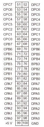
| • | The two 50-way plugs then plug into a Lafayette Instruments 81403 converter box. |
| • | From that emerge two 36-way Centronics-style cables (part 81405, with suffixes -6 or -25 for the length in feet), which plug into a Lafayette Instruments 81401 ABET starter interface, which also receives a 28 V DC power supply, via an 81410 power supply cable. This 81401 interface controls the first chamber (chamber number 1). It's impossible to plug the pairs of Centronics cables in backwards, since the gender orientation of each cable in the pair is different. |
| • | You can stack further interfaces (in the form of Lafayette Instruments 81402 expander interfaces) on top of the 81401 (they slot together). Each controls one operant chamber, numbered consecutively. Up to this point, the system is using 5 V TTL logic. |
| • | From each of the interfaces (81401 and 81402) emerge two 25-way cables (part 81406, with suffixes -10, -25, or -50 for the length in feet). From this point on, the system uses 28 V. The two 25-way cables from one 81401/81402 interface plug into a Lafayette Instruments 81408 full I/O module connection block, which has screw terminals that devices can be connected to (16 inputs and 32 outputs) plus 10 modular six-pin (RJ-25?) connectors to control intensity modules (intensity is controlled in "7 discrete steps", so this six-pin connector presumably has a three-bit intensity signal plus power and ground and something else each). It's impossible to plug the pairs of 25-way cables in backwards, since the gender orientation of each cable in the pair is different. |
| • | An alternative to the 81408 is an 81409 mini I/O module, which has screw terminals for 8 inputs and 15 outputs and 5 modular connectors for intensity modules. |
The electronic specifications for the ABET hardware are:
| • | Maximum number of interfaces: 16 |
| • | Per interface, maximum of 32 outputs, 16 inputs, 10 intensity modules. |
| • | RNC: Since only 50 pins go into the screw terminal block, and 32+16=48, I'd imagine that you can't use 32 outputs and 10 intensity modules independently. Yes, confirmed by the manual: Intensity block 1 uses output data lines 1-3; intensity block 2 uses outputs 4-6; intensity block 3 uses outputs 7-9; intensity block 4 uses outputs 10-12; intensity block 5 uses outputs 13-15; intensity block 6 uses outputs 16-18; intensity block 7 uses outputs 19-21; intensity block 8 uses outputs 22-24; intensity block 9 uses outputs 25-27; intensity block 10 uses outputs 28-30. |
| • | Supply voltage: minimum 22 V DC, maximum 35 V DC. |
| • | Quiescent current per interface: 40 mA. |
| • | Maximum output current per interface: 2 A. |
| • | Maximum current per output: 0.5 A. |
| • | Maximum output line voltage: 50 V DC. |
| • | Maximum input line voltage: 50 V DC. |
| • | Maximum length between computer and interface stack 25', and between interface stack and environments (operant chambers) 100'. |
| • | Power connector: 2.1 mm centre-positive DC jack |
| • | Timing resolution: 1 ms. |
The signal connections to actual devices work like this:
| • | An output device is connected to (1) a +28 V DC rail on the screw terminal, labelled "+28 VDC", and (2) the controlling terminal, labelled "OUTPUTS 1...32". Each ABET output line provides a connection to common or ground when it is activated (and is, presumably, not connected to anything when it is not activated). Output devices are described as being wired either with a two-wire connection (e.g. red = +28 V, black = output) or a three-wire connection (e.g. red = +28 V, white = output, black = common/ground). |
| • | An input device is connected to (1) a 0 V DC common/ground terminal, labelled "COMMON", and (2) the sensing terminal, labelled "INPUTS 1...16". The input lines are pulled up to a logic level high (actually about +4.5 V); the input devices must provide a switch closure to common (ground) to activate the input. Input devices are two-wire (e.g. red = input, black = common). |
So it's a "short-to-ground = active" system.
Multiplexing system for Lafayette/Campden ABET hardware
The 96-way digital I/O card is used to control up to 16 operant chambers, each with up to 16 inputs and 32 outputs. That's 48 lines per chamber, and therefore up to 768 devices. Clearly, some trickery is needed to get a 96-way card to control 768 devices, and that trickery is multiplexing. This is the system in use:
On the PCI-DIO-96: RNC:
Address outputs (4 bits): APA<3:0> Port 0.3 to port 0.0 - output
Output enable (1 bit): APA<4> Port 0.4 - output
Service request inputs: DPA<0:7>(chambers 1-8) Port 9 - input
DPB<0:7>(chambers 9-16) Port 10 - input
Data inputs: CPA<0:7>(inputs 1-8) Port 6 - input
CPB<0:7>(inputs 9-16) Port 7 - input
Data outputs: APB<0:7>(outputs 1-8) Port 1 - output
APC<0:7>(outputs 9-16) Port 2 - output
BPA<0:7>(outputs 17-24) Port 3 - output
BPB<0:7>(outputs 25-32) Port 4 - output
BPC (port 5) not used, or used for IRQs, it seems
CPC (port 8) not used, or used for IRQs
DPC (port 11) not used, or used for IRQs
Alternatively:
#define ABET_ADDRESS_OUTPUT_PORT 0 // port 0 = output (APA) - address outputs (bits 0-3) and output enable (bit 4)
#define ABET_DATA_OUTPUT_PORT_A 1 // port 1 = output (APB) - controlling selected chamber outputs 1-8
#define ABET_DATA_OUTPUT_PORT_B 2 // port 2 = output (APC) - controlling selected chamber outputs 9-16
#define ABET_DATA_OUTPUT_PORT_C 3 // port 3 = output (BPA) - controlling selected chamber outputs 17-24
#define ABET_DATA_OUTPUT_PORT_D 4 // port 4 = output (BPB) - controlling selected chamber outputs 25-32
#define ABET_UNUSED_PORT_A 5 // port 5 = UNUSED (BPC)
#define ABET_DATA_INPUT_PORT_A 6 // port 6 = input (CPA) - monitoring selected chamber inputs 1-8
#define ABET_DATA_INPUT_PORT_B 7 // port 7 = input (CPB) - monitoring selected chamber inputs 9-16
#define ABET_UNUSED_PORT_B 8 // port 8 = UNUSED (CPC)
#define ABET_SERVICEREQUESTPORT_A 9 // port 9 = input (DPA) - service request inputs for chambers 1-8
#define ABET_SERVICEREQUESTPORT_B 10 // port 10 = input (DPB) - service request inputs for chambers 9-16
#define ABET_UNUSED_PORT_C 11 // port 11 = UNUSED (DPC)
Additionally, Vern Davidson (vern@lafayetteinstrument.com) commented that "some of the I/O is used as an address for the ABET interfaces (81401 and 81402), while the rest of the I/O on the card are latched inputs from ABET interfaces, latched outputs... and interrupt requests (IRQs)". Now APC0, APC3, BPC0, BPC3, CPC0, CPC3, DPC0, DPC3 are the only pins that can generate interrupts - so maybe BPC, CPC, and/or DPC are used for interrupts (6 potential interrupt-generating lines).
The lines are active high (high voltage = on, low voltage = off).
The multiplexing system works like this:
"In the ABET software from Lafayette, the 16 service request lines are constantly monitored.
When an input to a chamber is activated, the service request line for that chamber goes high.
The time that occurs is recorded as the event time; the chamber is then addressed to determine which input occurred.
The address outputs are tied to a multiplexer:
0000 = chamber 1
0001 = chamber 2
0010 = chamber 3
etc.
The output enable line is used to latch the outputs on the addressed chamber, like this:
Set the address.
Set the outputs.
Pulse the output enable line.
The outputs are now latched.
Please note that the inputs are also latched. Pulsing the output enable line will reset the input latches, so it is necessary to read the inputs before setting the outputs."
Much fiddling with code, lightbulbs, and switches...
WE CAN'T DETECT OFF TRANSITIONS.
This must be what the multiplexer hardware (84101/84102 interface) does:
| • | Scan the physical hardware or respond automatically to ON transitions. (Perhaps the multiplexer itself has 82C55s in, and relies on their change-detection system? Otherwise it could perhaps respond to OFF transitions too...) |
| • | If an input line has gone ON, and the OUTPUT-ENABLE bit is clear, (1) set the [line corresponding to the] chamber's bit in the SERVICE-REQUEST port, (2) trigger an interrupt (somehow) to request service from software that relies on interrupts (note: Whisker doesn't rely on interrupts, and uses 1 kHz polling instead). |
| • | When the computer writes the ADDRESS-OUTPUT port, (1) latch the appropriate chamber's INPUT states - meaning the lines that have just gone on, i.e. the stored/pending transitions, not the lines that *are* on - into the DATA-INPUT lines. THINK OF THE INPUT PORT AS THE "PENDING ON-TRANSITION NOTIFICATION" PORT. |
| • | When the computer writes the OUTPUT-ENABLE bit, (1) copy the DATA-OUTPUT state into the chamber's output lines; (2) clear all on-transition notifications. |
| • | Note that the computer must clear the OUTPUT-ENABLE bit to allow the multiplexer to respond to inputs again (see above). |
Detecting OFF transitions using ABET hardware and Whisker
Whisker copes with the lack of OFF-detecting hardware like this:
| • | Lines that cannot detect OFF events respond to ON transitions by going on for a single poll (typically 1 ms). |
| • | You cannot set OFF events on an input line that does not detect them. (This is to prevent you from relying on OFF events whose timings -- one poll -- are fictional, and do not reflect the real-world device.) |
| • | You cannot read the state of an input line that cannot detect OFF events. In the status display, the number of on transitions is shown rather than the current state of the line. |
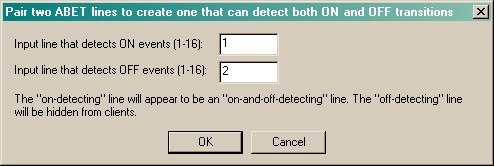
| • | You can dedicate a second line to detecting OFF events. You would wire these physically so that the device going on triggers an ON event on one line, and the device going off triggers an ON event on a second line. (Lafayette do this for their 80113 retractable lever, the only device they list that appears to notify the hardware of OFF events.) |
| • | Line can thus be paired: two physical lines that only detect ON events are combined to give a virtual line that responds to ON and OFF events. |
| • | The virtual line starts in the "off" state. |
| • | When the "on" line goes on, the virtual line goes on. When the "off" line goes on, the virtual line goes off. (If both go on simultaneously, the virtual line stays or goes off -- and neither an ON nor an OFF event is generated by the server if the line was previously off.) |
| • | The combined virtual line can be treated normally (i.e. you can set OFF events on it, and you can read its state). |
| • | The virtual line has the line number of the on-detecting line. The "off-detecting line" appears in a different colour on the server's display. It cannot be claimed, and it cannot be pegged (you can peg the corresponding virtual line instead). If you read its state on the console, it will read as OFF. |
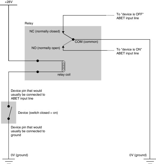
The easiest way to wire a device physically in order to make an "off-detecting" as well as an "on-detecting" line, using a device that shorts its signal line to ground when it goes on, would be like this, with a 28V relay (assuming the relay and device can cope with the resulting applied voltages!):
The ABET-II system
ABET-II changes the wiring system from ABET. In ABET, each operant chamber had 16 inputs and 32 outputs (the first 16 and the last 32 lines, respectively, within each group of 48 lines corresponding to each chamber, and numbered consecutively as you'd expect).
ABET-II dispenses with two outputs in each set of 48. Then, each set can either driver one operant chamber ("not split") or two ("split"), the splitting being done with a cable.
Within each of the (16) sets of 48 lines, then, the following wiring diagram is used:
ABET-II (not split)
| • | lines 0-15 = chamber inputs 0-15 |
| • | lines 16-47 = chamber outputs 0-31 (except that lines 31 and 47 are unused) |
ABET-II (split)
| • | lines 0-7 = chamber A inputs 0-7 |
| • | lines 8-15 = chamber B inputs 0-7 |
| • | lines 16-31 = chamber A outputs 0-14 plus one unused line (line 31) |
| • | lines 32-47 = chamber B outputs 0-14 plus one unused line (line 47) |
The "no-latch" system (probably to be called ABET-III or ABET-Touch)
The "no-latch" system is a modification to the ABET-II multiplexer (though it could in principle be applied to the ABET system as well). It removes the significant problem of not being able to detect "off" transitions.
See above for the description of how the multiplexer works normally - that is, when a device is activated, the input line and service request were set, and were cleared subsequently following a read of the inputs. The service request and input would not be set again until the device was deactivated and then reactivated.
In this modification, with the latches removed, the service request and input stay activated as long as the device is active. (Reading the service request and input will clear them but they will be set again immediately after reading.) When the device is deactivated released the corresponding input and resulting service request will clear upon reading and stay cleared.