This is a card that is sensitive to electrostatic discharge.
You must, as a minimum, wear an earthed wrist strap when handling the board outside its protective bag.
Additionally, analogue input voltages must never exceed ±15V when the system is powered on, or ±2V when it is off.
You must therefore connect unused inputs to ground before installation (see below).
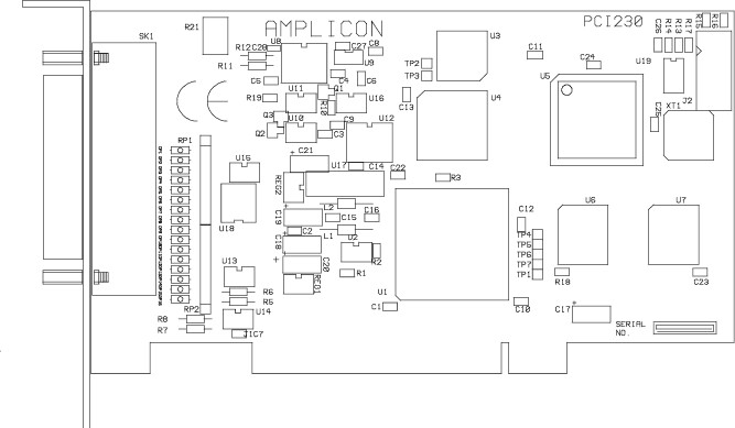
About the PCI230 card
This card has 16 analogue input lines (which can be paired to give 8 differential inputs); it will take input signals in the range ±10V. It can sample inputs at up to 312 kHz (across all channels, i.e. one channel at 312 kHz, two channels at 156 kHz, etc.) using a FIFO. It has two analogue outputs but these do not have FIFO buffers, so outputs must be driven directly by the software. The output resolution is 12-bit, in the range 0–10V or ±10V; therefore, the best output resolution is 2.4 mV. The board also has 24 digital I/O lines, and three timers/counters, but the timers/counters are not made available for users by Whisker.
Installing the PCI230 card
Read the notes above and below. Ensure the computer is off. Install the card into the computer.
Installing the PCI230 under Windows 2000
Turn the computer on; it will detect the card. Insert the Amplicon driver CD when Windows asks to search for a suitable driver (and ensure that the CD-ROM is ticked for it to search). Windows will assign an IRQ (interrupt request) number to the card automatically. To check this, choose Start → Control Panel → System → Hardware → Device Manager. Ensure View devices by type is ticked. Under Amplicon Analogue/Digital IO Counter Timer Cards, you should find the PCI230 card. Click Properties. Check that it has been assigned an IRQ and a DIO number and there are no resource conflicts.
Connecting the PCI230 to devices
Connections for the PCI230 (viewed from the rear, i.e. looking at the socket) and the optional screw terminal assembly are shown below. "Channel" refers to analogue input channels; "Port" refers to digital I/O ports.
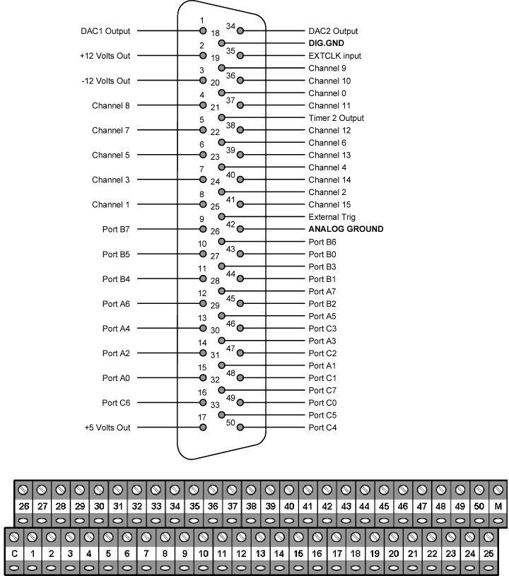
On the screw terminal assembly, terminal M is connected to the shell of the D-type connector (which, on the PCI230 itself, is connected to the computer's chassis ground). Terminal C is not connected.
| • | Analogue input voltages must never exceed ±15 V when the system is powered on, or ±2 V when it is off. Therefore, you should connect any unused (floating) input channels to the analogue signal ground. You should also avoid having a signal present on an input when the computer is being switched on or off. Specifically, this means that apart from any pins corresponding to channels you are using, you should connect pins 4, 5, 6, 7, 8, 19, 20, 22, 23, 24, 36, 37, 38, 39, 40, and 41 (channels 0-15, not in order) to pin 42 (analogue ground). |
| • | Use separate ground wires for analogue input, analogue output, digital I/O, and power. Use a heavy-gauge wire for the ground connector. Try to keep the ground point close to the PCI224 terminal block to minimize ground impedance. If your input lines are long, shield them. |
| • | Devices connected to the analogue inputs must have a source impedance of less than 250 Ω. |
| • | Analogue inputs must not exceed the voltage for the selected input range. |