This is a card that is sensitive to electrostatic discharge.
You must, as a minimum, wear an earthed wrist strap when handling the board outside its protective bag.
About the PCI224 card
This card has 16 analogue output lines, each with 12-bit resolution (giving 4096 levels of output voltage). Its range can be set to ±10V, ±5V, ±2.5V, ±1.25V (bipolar), or 0–10V, 0–5V, 0–2.5V, 0–1.25V (unipolar). Therefore its best resolution (using the 0–1.25V range) is 0.3 mV. Its worst resolution (using the ±10V range) is 4.9 mV. It has no input channels.
Installing the PCI224 card
Ensure the computer is off. Install the card into the computer.
Installing the PCI224 under Windows 2000
Turn the computer on; it will detect the card. Insert the Amplicon driver CD when Windows asks to search for a suitable driver (and ensure that the CD-ROM is ticked for it to search). Windows will assign an IRQ (interrupt request) number to the card automatically. To check this, choose Start → Control Panel → System → Hardware → Device Manager. Ensure View devices by type is ticked. Under Amplicon Analogue/Digital IO Counter Timer Cards, you should find the PCI224 card. Click Properties. Check that it has been assigned an IRQ and a DIO number and there are no resource conflicts.
Connecting the PCI224 to devices
Connections for the PCI224 and the optional screw terminal assembly are shown below.
Pin |
|||
EXTCLK |
1 |
|
|
EXTTRIG |
2 |
20 |
OUT2 |
EXTREF |
3 |
21 |
DGND |
DAC0 |
4 |
22 |
AGND |
DAC1 |
5 |
23 |
AGND |
DAC2 |
6 |
24 |
AGND |
DAC3 |
7 |
25 |
AGND |
DAC4 |
8 |
26 |
AGND |
DAC5 |
9 |
27 |
AGND |
DAC6 |
10 |
28 |
AGND |
DAC7 |
11 |
29 |
AGND |
DAC8 |
12 |
30 |
AGND |
DAC9 |
13 |
31 |
AGND |
DAC10 |
14 |
32 |
AGND |
DAC11 |
15 |
33 |
AGND |
DAC12 |
16 |
34 |
AGND |
DAC13 |
17 |
35 |
AGND |
DAC14 |
18 |
36 |
AGND |
DAC15 |
19 |
37 |
AGND |
(EXTTRIG - external trigger input for DACs; DAC0-15 - digital to analogue converter outputs; EXTCLK - external clock input; OUT2 - timer 2 output; DGND - digital ground; AGND - analogue ground.) The analogue outputs and ground are paired (e.g. DAC0 is paired with pin 22 AGND, DAC1 with pin 23 AGND, etc.).
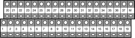
On the screw terminal assembly, terminal M is connected to the shell of the D-type connector (which, on the PCI224 itself, is connected to the computer's chassis ground). Terminal C (which may be present to the left of terminal 20 - not shown above) is not connected.
| • | Use separate ground wires for analogue output, digital I/O, and power lines. Use heavy-gauge wire for the ground connection. Try to have the ground point close to the PCI224 terminal block to minimize ground impedance. If output lines are long, shield them. |
| • | All devices connected to the analogue outputs must have a minimum load impedance of at least 2 kΩ. |
| • | The output impedance of the PCI224 is 50 Ω and this should be matched on the user's equipment. |