Message
DisplayAddObject <docname> <objectname> <objecttype> <parameters…>
Originator
Client
Response
General:
SyntaxError: insufficient parameters to DisplayAddObject
SyntaxError: invalid parameters to DisplayAddObject
Error: document docname not found by DisplayAddObject
Error: unknown object type
Bitmaps:
SyntaxError: insufficient parameters to DisplayAddObject / bitmap
SyntaxError: stretched object of zero size (DisplayAddObject/bitmap)
Error: can't create bitmap
Error: bitmap has problems, deleting it
Info: bitmap added
Other responses are also possible for video object types; see DisplayAddObject: video.
Response (immediate socket)
Success
Failure
Details
Adds an object named objectname to the document named docname. The object may be of several types, listed below. The parameters differ for each type of object.
If a parameter includes spaces or semicolons, enclose it in quotes ("").
OBJECTTYPE = video
For video, see DisplayAddObject: video.
OBJECTTYPE = text
PARAMETERS = <x> <y> <text> [-height <height>] [-font <font>] [-textcolour <red> <green> <blue>] [-backcolour <red> <green> <blue>] [-opaque] [-italic] [-underline] [-weight <weight>] [-top | -baseline | -middle | -bottom] [-left | -centre | -right]
Inserts text.
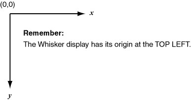
| • | x = x-coordinate of (by default) the top left point; the meaning of these coordinates can be changed by the vertical/horizontal alignment options below |
| • | y = y-coordinate of (by default) the top left point; the meaning of these coordinates can be changed by the vertical/horizontal alignment options below |
| • | text = text to be displayed. Enclose the text in double-quotes if necessary. |
| • | height = height of the font (0, the default, gives you a reasonable size) |
| • | font = name of the font to use, e.g. "Times New Roman" (use quotes as the font name has spaces in it). If no font is specified, or if the font you specify cannot be found, a default system font is used. |
| • | textcolour = text colour (red, green, blue take values from 0–255). Default colour is white (255,255,255). |
| • | backcolour = background colour, if used. Default colour is black (0,0,0). Only relevant if the background mode is 'opaque'. |
| • | –opaque sets opaque background mode. Opaque mode fills in the 'gaps' with the background colour; transparent mode allows you to see through the gaps in the text. Default is transparent. |
| • | –italic makes the font italic |
| • | –underline underlines the font |
| • | weight = number from 1–1000 to specify an approximate font weight (how bold it is), or 0 to specify a default weight (which is, perhaps not surprisingly, the default). |
| • | –top | –baseline | –middle | –bottom determines the vertical alignment (default is top). The top (ascent line), baseline, middle (vertical centre) or bottom (descent line) of the text can be aligned to the y coordinate. (What's the difference between baseline and bottom? Look at the letter y: it descends below the baseline of the text.) |
| • | –left | –centre | –right determines the horizontal alignment (default is left). The left edge, centre, or right edge of the text can be aligned to the x coordinate. |
The precise horizontal position and extent of the text depends upon whether it is opaque or not, although the difference will not be visible except for very large text.
| • | If it is opaque, the background rectangle will be exactly aligned to the coordinates given, and GetObjectExtent will return the rectangle painted with background colour (including any background painted at the left and right edges. |
| • | If it is not opaque, the text characters will be exactly aligned to the coordinates given, and GetObjectExtent will return the rectangle of a close surrounding (horizontally) rectangle. |
Example figures showing the alignment (black lines are coordinates, white rectangles are extents of text objects):
OBJECTTYPE = bitmap
PARAMETERS = <x> <y> <filename> [-stretch|-clip] [-height <height>] [-width <width>] [-top | -middle | -bottom] [-left | -centre | -right]
Inserts a bitmap from a file.
| • | x = x-coordinate of (by default) the top left point; the meaning of these coordinates can be changed by the vertical/horizontal alignment options below |
| • | y = y-coordinate of (by default) the top left point; the meaning of these coordinates can be changed by the vertical/horizontal alignment options below |
| • | filename = filename of bitmap |
| • | width = width to display bitmap at, –1 for the bitmap's own width (default) |
| • | height = height to display bitmap at, –1 for the bitmap's own height (default) |
| • | –stretch|–clip: stretch or clip bitmap (clipping is the default). |
| • | –top | –middle | –bottom determines the vertical alignment (default is top). The top, middle (vertical centre), or bottom of the bitmap can be aligned to the y coordinate. |
| • | –left | –centre | –right determines the horizontal alignment (default is left). The left edge, centre, or right edge of the bitmap can be aligned to the x coordinate. |
OBJECTTYPE = line
PARAMETERS = <x1> <y1> <x2> <y2> [<pen_options>]
Draws a line from (x1, y1) to (x2, y2).
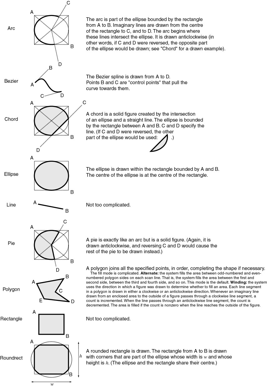
OBJECTTYPE = arc
PARAMETERS = <x1> <y1> <x2> <y2> <x3> <y3> <x4> <y4> [<pen_options>]
Draws an arc that fits within the rectangle (x1, y1)–(x2, y2). The arc begins at (x3, y3) and ends at (x4, y4), approximately. As the Windows GDI documentation states, this function 'draws an elliptical arc. The arc drawn by using the function is a segment of the ellipse defined by the specified bounding rectangle. The actual starting point of the arc is the point at which a ray drawn from the center of the bounding rectangle through the specified starting point intersects the ellipse. The actual ending point of the arc is the point at which a ray drawn from the center of the bounding rectangle through the specified ending point intersects the ellipse. The arc is drawn in [an anticlockwise] direction.'
OBJECTTYPE = bezier
PARAMETERS = <x1> <y1> <x2> <y2> <x3> <y3> <x4> <y4> [<pen_options>]
Draws a cubic Bézier spline. The curve is drawn from (x1, y1) to (x4, y4); the points (x2, y2) and (x3, y3) are control points (that 'pull' the curve towards them).
OBJECTTYPE = chord
PARAMETERS = <x1> <y1> <x2> <y2> <x3> <y3> <x4> <y4> [<pen_options>] [<brush_options>]
Draws a chord (a closed figure bounded by the intersection of an ellipse and a line segment). The (x1, y1) and (x2, y2) parameters specify the upper-left and lower-right corners, respectively, of a rectangle bounding the ellipse that is part of the chord. The (x3, y3) and (x4, y4) parameters specify the endpoints of a line that intersects the ellipse.
This function takes the pen and brush options described below.
OBJECTTYPE = ellipse
PARAMETERS = <x1> <y1> <x2> <y2> [<pen_options>] [<brush_options>]
Draws an ellipse that fits within the rectangle (x1, y1)–(x2, y2). The centre of the ellipse is at the centre of this rectangle.
OBJECTTYPE = pie
PARAMETERS = <x1> <y1> <x2> <y2> <x3> <y3> <x4> <y4> [<pen_options>] [<brush_options>]
Draws a pie-shaped wedge by drawing an elliptical arc whose center and two endpoints are joined by lines. The center of the arc is the center of the bounding rectangle (x1, y1)–(x2, y2). The starting and ending points of the arc are specified by (x3, y3) and (x4, y4).
The arc is drawn anticlockwise. Two additional lines are drawn from each endpoint to the arc's center. The pie-shaped area is then filled. If (x3, y3) = (x4, y4), the result is an ellipse with a single line from the center of the ellipse to the point (x3, y3) or (x4, y4).
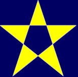
OBJECTTYPE = polygon
PARAMETERS = <numpoints> <x1> <y1> <x2> <y2> <x3> <y3> <...> <...> [-alternate|-winding] [<pen_options>] [<brush_options>]
Draws a polygon (x1, y1)–(x2, y2)–(x3, y3)–… Numpoints specifies the total number of (x, y) points. The polygon is closed, if necessary, by joining the last point to the first.
Polygons may be filled in one of two ways. As the Windows GDI documentation describes:
| • | –alternate: the system fills the area between odd-numbered and even-numbered polygon sides on each scan line. That is, the system fills the area between the first and second side, between the third and fourth side, and so on. This mode is the default. |
| • | –winding: the system uses the direction in which a figure was drawn to determine whether to fill an area. Each line segment in a polygon is drawn in either a clockwise or an anticlockwise direction. Whenever an imaginary line drawn from an enclosed area to the outside of a figure passes through a clockwise line segment, a count is incremented. When the line passes through an anticlockwise line segment, the count is decremented. The area is filled if the count is nonzero when the line reaches the outside of the figure. |
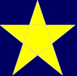
The following figures illustrate the two filling methods; the five points of the pentacle were drawn in the order top → bottom left → right → left → bottom right.
Alternate
|
Winding
|
OBJECTTYPE = rectangle
PARAMETERS = <x1> <y1> <x2> <y2> [<pen_options>] [<brush_options>]
Draws a rectangle from (x1, y1) to (x2, y2).
OBJECTTYPE = roundrect
PARAMETERS = <x1> <y1> <x2> <y2> <x3> <y3> [<pen_options>] [<brush_options>]
Draws a rounded rectangle. The rectangle (x1, y1)–(x2, y2) is drawn but with corners that are part of an ellipse whose width is x3 and whose height is y3.
OBJECTTYPE = camcogquadpattern
PARAMETERS = <x1> <y1> <pixelwidth> <pixelheight> <topleft1>...<topleft8> <topright1>...<topright8> <bottomleft1>...<bottomleft8> <bottomright1>...<bottomright8> <topleftred> <topleftgreen> <topleftblue> <toprightred> <toprightgreen> <toprightblue> <bottomleftred> <bottomleftgreen> <bottomleftblue> <bottomrightred> <bottomrightgreen> <bottomrightblue> <backgroundred> <backgroundgreen> <backgroundblue>
Draws a pattern composed of four quadrants, each made up of 8x8 small rectangles (pixels). For each quadrant, eight rows are specified; each row's pattern is specified by a single number from 0 to 255, of which the high bit represents the left-hand pixel and the low bit the right-hand pixel.
Pen options
Objects that consist of or are bounded by lines (i.e. line, arc, bezier, chord, ellipse, pie, polygon, rectangle, roundrect) are drawn with the following pen options:
-penstyle solid|dash|dot|dashdot|dashdotdot|null|insideframe
-penwidth <width>
-pencolour <red> <green> <blue>
The options solid, dash, dot, dashdot, and dashdotdot should be fairly self-explanatory. Null gives an invisible pen. Insideframe is relevant when the pen is thick; for example, if you draw a circle of diameter 100 units with a pen of width 20 units, the circle will normally end up having an external diameter of 120 units and an internal diameter of 80 units (as the pen overlaps by 10 units on the inside and the outside of the circle). If you specify insideframe, the circle's outside diameter is 100 units in this situation.
The default is a solid white pen of width 1.
Brush options
Solid figures (chord, ellipse, pie, polygon, rectangle, roundrect) all take brush options. The brush options determine how the object is filled. A brush may be hollow (invisible), solid, or hatched (in which case you can specify the hatching style and colour). The default is a solid white brush.
-brushhollow
-brushsolid <red> <green> <blue>
-brushhatched bdiagonal|cross|diagcross|fdiagonal| horizontal|vertical <red> <green> <blue>
The hatching styles are:
| • | bdiagonal: lines at 45° anticlockwise from the horizontal axis; |
| • | cross: horizontal and vertical lines; |
| • | diagcross: lines at 45° clockwise and anticlockwise from the horizontal; |
| • | fdiagonal: lines at 45° clockwise to the horizontal; |
| • | horizontal: horizontal lines; |
| • | vertical: vertical lines. |
If a hatched brush is used, further options come into play. A hatched brush may either be opaque or transparent. If it is transparent, you can see through the hatching to whatever is beneath. If it is opaque, you may set the background colour used to fill in the gaps in the hatching. (The default settings for a hatched brush are for it to be opaque with black as the background colour.)
-brushtransparent
-brushopaque
-brushbackground <red> <green> <blue>
The coordinate system
Geometrical object types
Touch-/mouse-sensitive areas of objects
Objects that have a painted area can be set to generate events if mouse or touchscreen events over that area, by means DisplaySetEvent.
Object types with painted areas are Bitmap, Ellipse, Chord, Pie, Rectangle, RoundRect, Polygon and Text.
Line, Arc and Bezier objects cannot be used as touch- or mouse-sensitive areas.
Examples
For a document called Wanda…
displayaddobject wanda apple bitmap 50 50 \\coffee.bmp
displayaddobject wanda pear bitmap 100 100 \\santa_fe.bmp
displayaddobject wanda objtext text 150 150 "Test document: Wanda" -height 100 -font "times new roman" -italic
displayaddobject wanda objline line 50 50 200 600
displayaddobject wanda objarc arc 100 100 400 400 150 100 350 100 -penwidth 5 -pencolour 100 0 0 -penstyle dash
displayaddobject wanda objbezier bezier 100 100 100 400 400 100 400 400 -penstyle dash
displayaddobject wanda objchord chord 300 300 500 500 300 350 500 350 -penstyle insideframe -pencolour 0 100 0 -penwidth 5 -brushsolid 50 50 0
displayaddobject wanda objellipse ellipse 650 100 750 400 -brushhollow
displayaddobject wanda objpie pie 600 300 800 500 800 300 800 500 -brushhatched bdiagonal 128 128 128 -brushopaque -brushbackground 255 255 0
displayaddobject wanda objrect rectangle 250 550 150 450 -penstyle dashdotdot -brushsolid 128 128 128
displayaddobject wanda objroundrect roundrect 400 450 500 550 100 100 -brushhatched cross 255 255 0 -brushtransparent -brushbackground 255 0 255
displayaddobject wanda objpolygon polygon 3 400 500 600 450 600 550 -brushhatched horizontal 255 255 0 -brushtransparent -brushbackground 255 0 255
displayaddobject wanda objpolygon2 polygon 5 150 425 75 650 250 500 50 500 225 650 -alternate -brushsolid 255 255 0
Revision history
Implemented by WhiskerServer version 2.3.
CamcogQuadPattern added in v2.6.8.
Text alignment and touching added in v 2.11
Video added in v4.0
Vertical and horizontal alignment options for bitmaps and video added in v4.2.1.
See also