Every system that has a device that could be dangerous if accidentally switched on or off should have a fail-safe device installed.
Note also that Whisker is a system designed for research purposes only, and should never be used to control medical apparatus or other devices that could endanger human life.
Parts required
| • | 24V 10A 3.5mm PCB power relay, RS part no. 229–3614, £2.75 each |
| • | DIN rail mounting socket for 3.5mm PCB relay, RS part no. 400–4129, £3.07 each |
| • | LED power monitor module for mounting socket, RS part no. 400–4056, £2.59 each |
Wiring the system
Designate two dedicated outputs on your system for fail-safe outputs. Call them X and Y.
Wire them as follows:
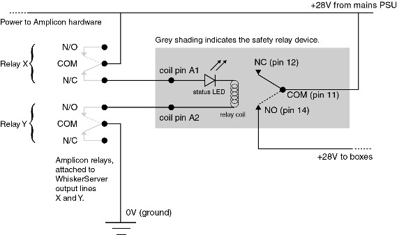
(Note: this high-power relay will not run from the 5V TTL outputs on the Amplicon EX233 distribution board.)
Controlling the power
| • | Wire the main box PSU to the COMmon pin of relay X. |
| • | Wire the N/C (normally closed) pin of relay Y to one of the safety relay coil pins. |
| • | Wire the other safety relay coil pin to the N/O (normally open) pin of relay Y. |
| • | Wire the COMmon pin of relay Y to ground. |
The N/O pin of relay X isn't used and mustn't be connected to anything.
The N/C pin of relay Y isn't used and mustn't be connected to anything.
Thus, when relay X is off and relay Y is on, current flows to the safety relay's coil.
Power to the devices
| • | Wire the main box PSU to the COMmon pin of the safety relay. |
| • | Wire the N/O (normally open) pin of the safety relay to your boxes' 24V power line. |
Thus, the boxes only get power when X is off and Y is on.
Configure WhiskerServer
The WhiskerServer program should be configured (Configure hardware → Configure failsafe outputs) so that
| • | the output line attached to relay X is OFF during operation; |
| • | the output line attached to relay Y is ON during operation; |
| • | some other state pertains when the server is not running (e.g. both relays off). |
See also